|
In electricity generation, an electric generator is a device that converts mechanical energy to electrical energy. The reverse conversion of electrical energy into mechanical energy is done by a motor; motors and generators have many similarities. A generator forces electrons in the windings to flow through the external electrical circuit. It is somewhat analogous to a water pump, which creates a flow of water but does not create the water inside. The source of mechanical energy may be a reciprocating or turbine steam engine, water falling through a turbine or waterwheel, an internal combustion engine, a wind turbine, a hand crank, compressed air or any other source of mechanical energy. 
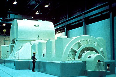
U.S. NRC image of a modern steam turbine generator Faraday’s disk 
Dynamos are no longer used for power generation due to the size and complexity of the commutator needed for high power applications. This large belt-driven high-current dynamo produced 310 amperes at 7 volts, or 2,170 watts, when spinning at 1400 RPM. 
Dynamo Electric Machine (U.S. Patent 284,110) The two main parts of a generator or motor can be described in either mechanical or electrical terms: Mechanical:
Electrical:
Because power transferred into the field circuit is much less than in the armature circuit, AC generators nearly always have the field winding on the rotor and the stator as the armature winding. Only a small amount of field current must be transferred to the moving rotor, using slip rings. Direct current machines (dynamos) require a commutator on the rotating shaft to convert the alternating current produced by the armature to direct current, so the armature winding is on the rotor of the machine.

Rotor from generator at Hoover Dam, United States 
A small early 1900s 75 KVA direct-driven power station AC alternator, with a separate belt-driven exciter generator. Main article: Excitation (magnetic)
A transformer is a device that transfers electrical energy from one circuit to another through inductively coupled conductorsâ€â€the transformer’s coils. A varying current in the first or primary winding creates a varying magnetic flux in the transformer’s core and thus a varying magnetic field through the secondary winding. This varying magnetic field induces a varying electromotive force (EMF) or "voltage" in the secondary winding. This effect is called mutual induction. If a load is connected to the secondary, an electric current will flow in the secondary winding and electrical energy will be transferred from the primary circuit through the transformer to the load. In an ideal transformer, the induced voltage in the secondary winding (Vs) is in proportion to the primary voltage (Vp), and is given by the ratio of the number of turns in the secondary (Ns) to the number of turns in the primary (Np) as follows: By appropriate selection of the ratio of turns, a transformer thus allows an alternating current (AC) voltage to be "stepped up" by making Ns greater than Np, or "stepped down" by making Ns less than Np. In the vast majority of transformers, the windings are coils wound around a ferromagnetic core, air-core transformers being a notable exception. Transformers range in size from a thumbnail-sized coupling transformer hidden inside a stage microphone to huge units weighing hundreds of tons used to interconnect portions of power grids. All operate with the same basic principles, although the range of designs is wide. While new technologies have eliminated the need for transformers in some electronic circuits, transformers are still found in nearly all electronic devices designed for household ("mains") voltage. Transformers are essential for high voltage power transmission, which makes long distance transmission economically practical 
Pole-mounted "split-phase" transformer with center-tapped secondary winding (note use of grounded conductor, right, as one leg of the primary feeder) The phenomenon of electromagnetic induction was discovered independently by Michael Faraday and Joseph Henry in 1831. However, Faraday was the first to publish the results of his experiments and thus receive credit for the discovery. The relationship between electromotive force (EMF) or "voltage" and magnetic flux was formalized in an equation now referred to as "Faraday’s law of induction":
where Faraday performed the first experiments on induction between coils of wire, including winding a pair of coils around an iron ring, thus creating the first toroidal closed-core transformer. 
Drawing of Ganz Company’s 1885 prototype. Capacity: 1400 VA, frequency: 40 Hz, voltage ratio: 120/72 V
From Wikipedia, the free encyclopedia : Manufacture of electric motors, generators and transformers |


 .
.  is the magnitude of the EMF in volts and ΦB is the
